Vechicular CO Dection
Introduction
CO is undetectable to the human senses, leading to many deaths every year. Non-traffic, unintentional CO poisoning from vehicle exhaust averaged an estimated 2,000 injuries from 2003–2006. Outbreaks of CO poisoning often occur during winter and extreme weather events (e.g., hurricanes, snowstorms, blizzards) because of motor vehicles left running in a closed environment[1]. Such a breathtaking number draws our attention. Incomplete combustion of fuel produces a huge amount of carbon monoxide. It’s extremely dangerous for passengers and the driver, especially with a defective exhaust system and unsealed car body.
This project focuses on the CO detection and initial response system for vehicles. CO detection system is designed to collect information of CO concentration, the status of engine, and the occupancy of people in car. If CO detection system finds CO concentration in the car is determined to be unsafe, the initial response system will be triggered to alarm the driver and passengers and circulate the air in the car to ensure the safety of people. We use CO sensor, temperature sensor and photoresistor sensor to verify a true danger. The initial response system includes multiple alarms.
Motivation
When CO density exceeds a certain threshold, our body replaces the oxygen in your red blood cells with carbon monoxide, which can lead to serious tissue damage, or even death[2]. The CO produced by internal combustion gasoline engines is up to 30,000 parts per million (ppm). So it’s dangerous for a vehicle with a defective exhaust system where CO leaks from and enters the vehicle through holes in the body or open windows[3]. Therefore, we decided to develop a CO detection and initial response system to initially reduce or lift danger and fight for rescue time.
Goals
We installed a CO sensor and a motion sensor in the car cabinet and a temperature sensor in the exhaust pipe.
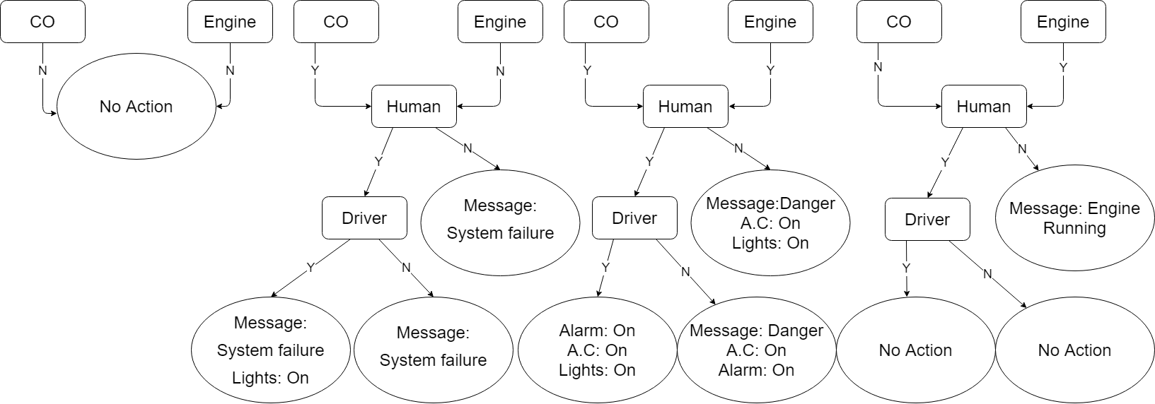
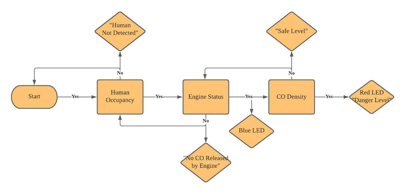
If the CO density is high enough to be determined dangerous, the initial response system will be triggered. If the motion sensor detects the driver in the car, the initial response system will turn on the in-vehicle alarm and the air conditioning system. If there’s only passengers or no people in the car, the initial response system will send an emergency message to the driver besides the in-vehicle alarm and the air conditioning system. But considering that CO poisoning is a low possibility event, we add an extra temperature sensor for engine status check to verify that the high CO density is caused by the engine instead of a system failure. That is to say, the situation will be defined as dangerous when the CO concentration is high with the engine running. The corresponding action of the initial response system will be determined based on human occupancy. The flow chart is attached below.
However, out of safety concerns, we will measure humidity instead of CO. Note that for the rest of the report, the target gas will still be addressed as CO even though it is humidity that is actually being measured.
Progress Report
09/15/2021
Our group set up the goal of the project, which is to detect the CO concentration in the closed environment and send an alarm to the user who is in this closed environment. The principle of our project is to protect human life by letting them know whether the CO concentration is in danger level. We assumed the vehicle is a closed environment for our testing purpose.
09/22/2021
Based on the principle of the project, our second meeting focusing on discussing the logic of CO detection and alarming system. As shown in Figure 1, our decision-making map has been created.From Figure 1, we made serval conditions that may occur during the real-life situation. But the major part is still the CO concentration sensor. Other decision circles like Message will be expressed by using light. The engine on/off status will be detected by the temperature sensor. Meanwhile, we determine the sensor we are potential going to use are:
- HC-SR501 PIR Motion Sensor
- DHT 11 Temperature and Humidity Sensor
- LED Light(s)
- MQ-7 CO Carbon Monoxide Detector Sensor
09/30/2021
After talked with Professor Berges about our project, especially the feasibility of CO concentration sensor data collection. We found that the environment in which we decided to collect the CO concentration data has potential extreme danger, and also, we don’t have a vehicle to create a closed environment for our test.
As a concession, we decide to use humidity as a substitution for CO. In the rest of the circuit setup, we will not use the MQ-7 CO concentration sensor but use DHT 11 to collect humidity instead.
10/01/2021
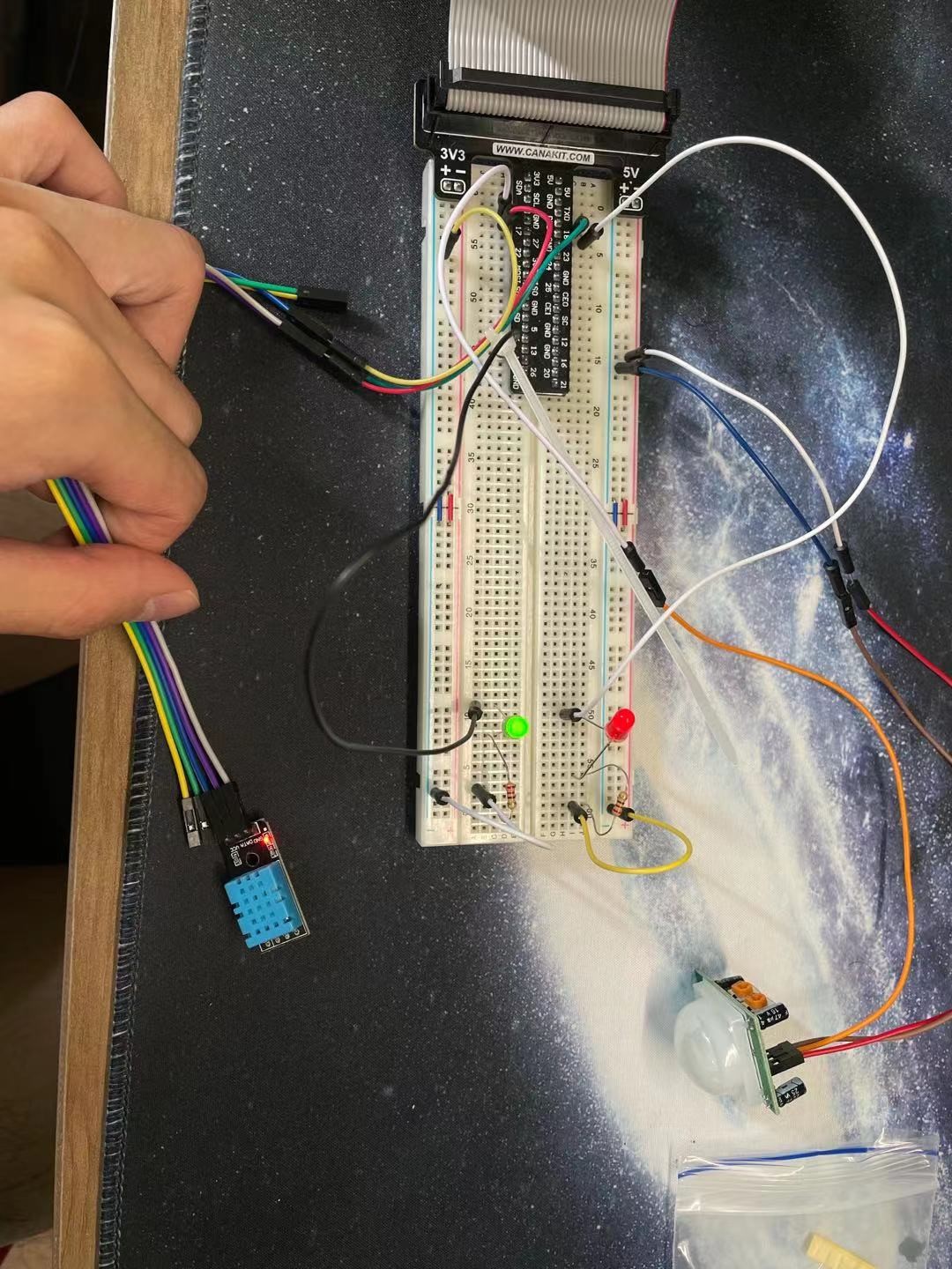
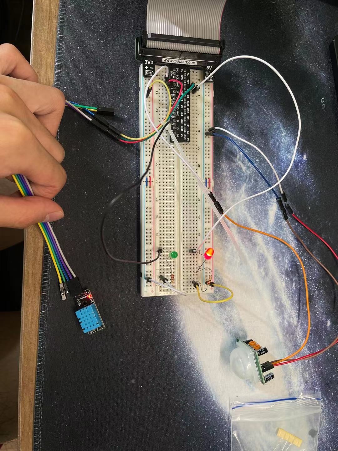
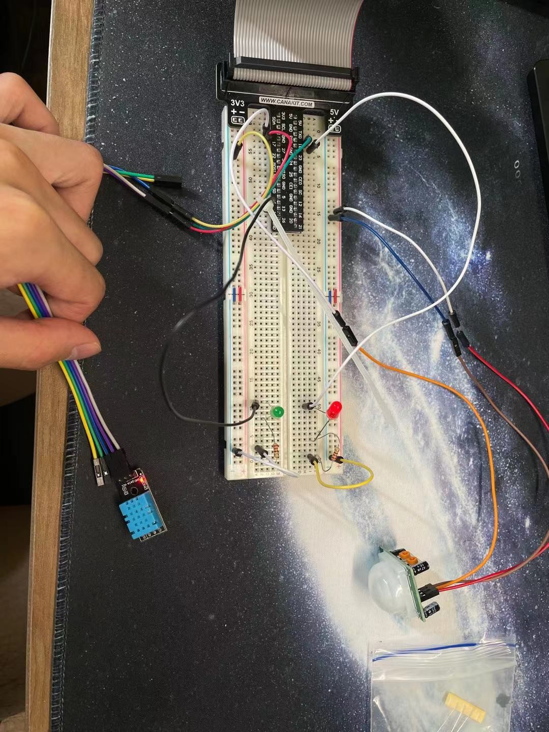
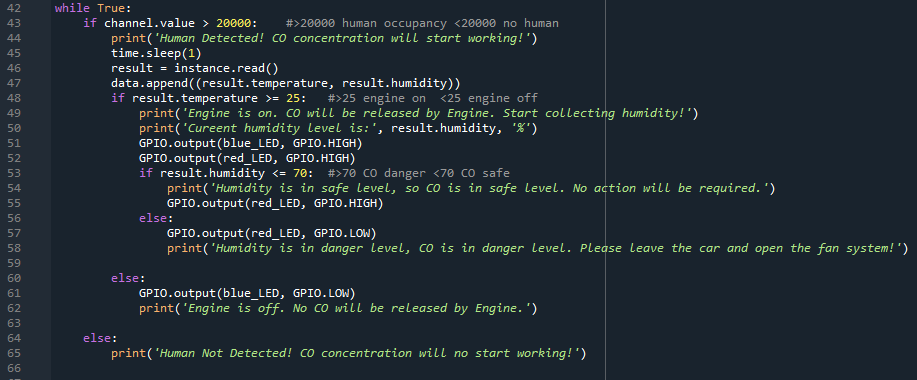
First attempt to set up the circuit by using Raspberry Pi 4 and sensors. We first use a motion sensor, 1 LED light, DHT-11 sensor to create a simple circuit to check whether all sensors are working properly.
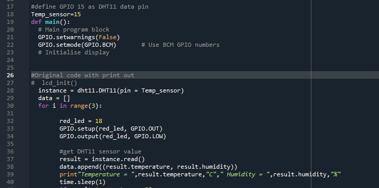
From Figure 2 and 3, we will use the print function in Python code to print the collected temperature and humidity and print “Motion Detected!” if the motion sensor returns the “True” value. “True” value will only be returned once the motion sensor detects motion in the detection range. Based on the output, we think all the sensors work properly.
Then we added 2 LED lights to show the working status; green LED will on if the DHT 11 is collecting data in Figure 4, then turn off once the DHT 11 stop working in Figure 5. Red LED will on once the motion has been detected by a sensor in Figure 6, turned off when there is no motion detected in Figure 7.

10/02/2021-10/08/2021
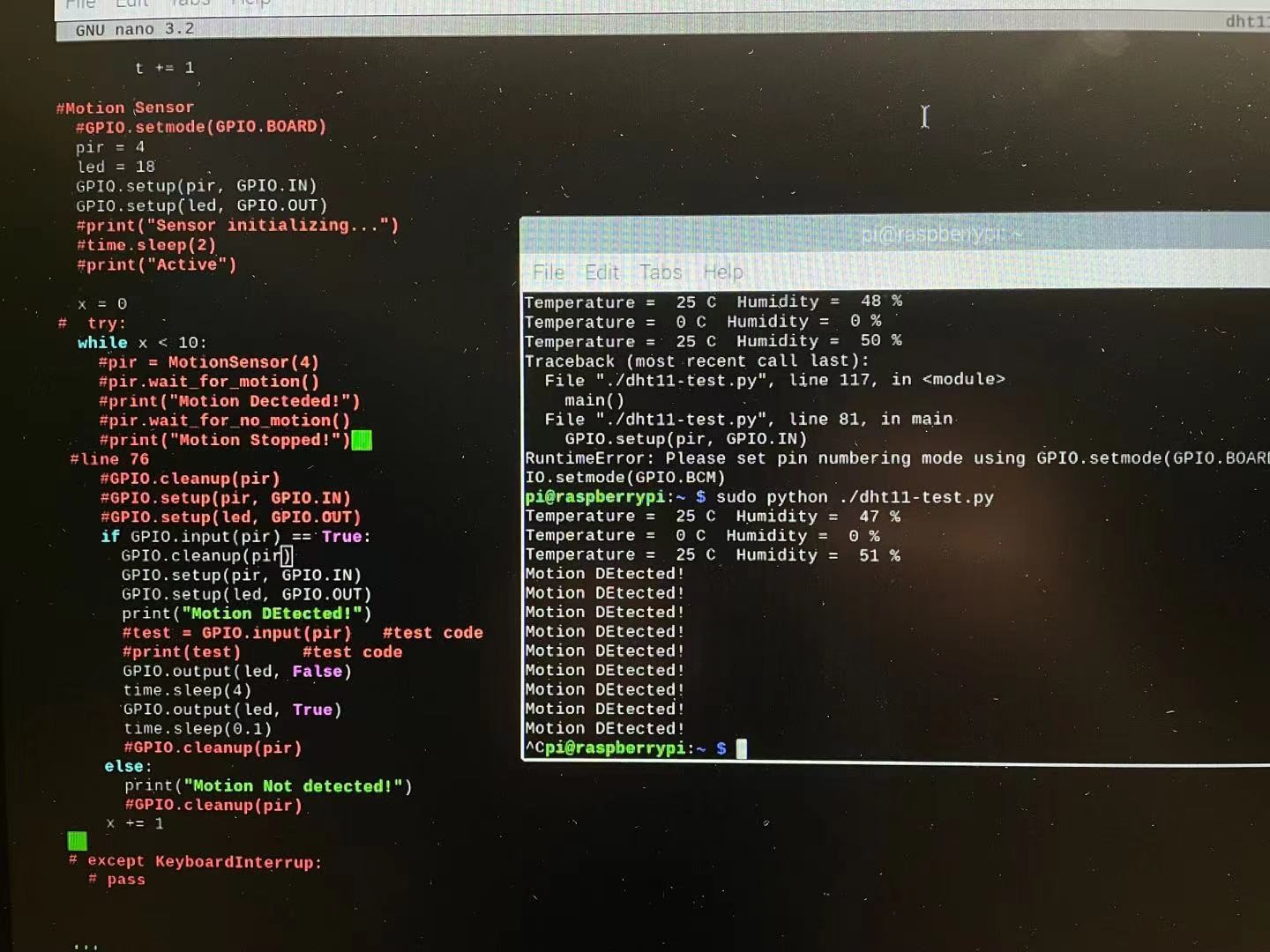
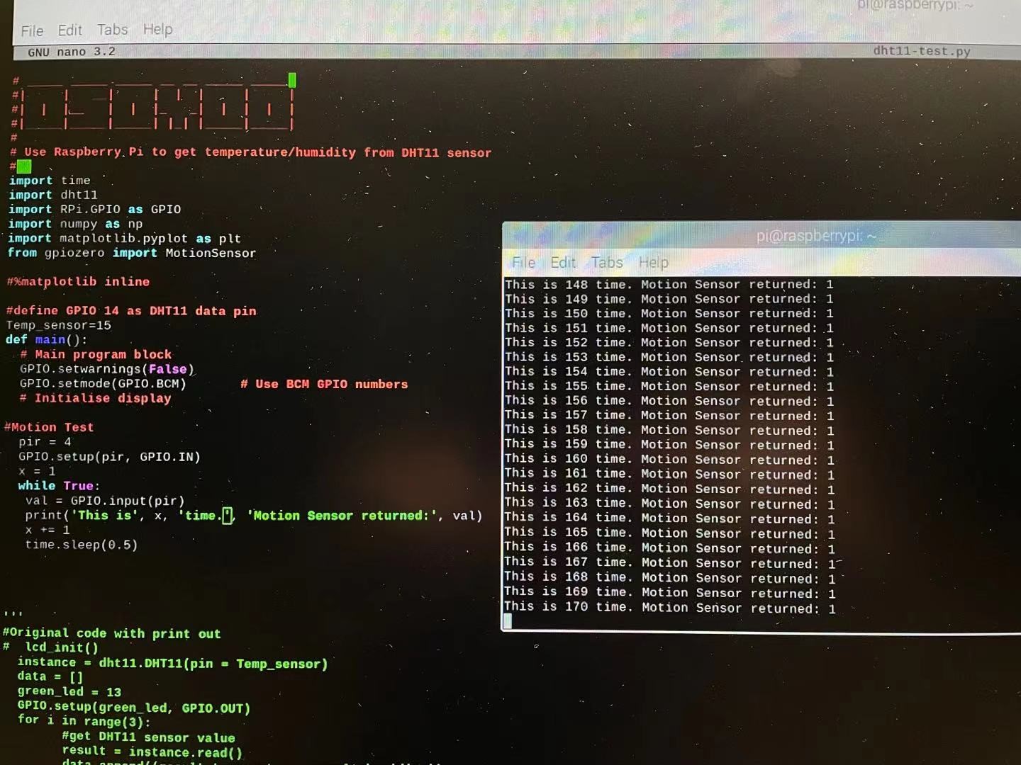
Optimizing the logical and decision-making process, we used red LED while the DHT11 was collecting data and green LED on while the motion sensor was working. While testing the motion sensor with no motion detection, a problem was found. The motion sensor keeps returning a True value even if there is no motion in the detection range.
A potential problem that may cause the failure in motion sensor returned value:
- Motion sensor return certain float numbers that will cause if function always true.
- Use while loop to print the input value from motion sensor at the time period of 1s, the code and running result is in Figure 8.
- After printing, we found that the motion sensor always returns 1 for either motion detected or motion not detected situation.
- We think the problem is caused by the sensor itself, since it only returns 1 value.
- Sensitivity is too high so that the motion will be detected any time. (×)
- Use a 3mm straight screwdriver to return sensitivity counterclockwise to reduce the sensitivity as much low as we can.
- Adjusting sensitivity in both counterclockwise and clockwise during the sensor is working, try to find a “motion no detected” situation where the sensor will return a False result.
- Time delay is too high that the motion sensor has no time to return other value. (×)
- Use a 3mm straight screwdriver to return sensitivity counterclockwise to reduce the sensitivity as much low as we can.
- Adjusting sensitivity in both counterclockwise and clockwise during the sensor is working, try to find a “motion no detected” situation where the sensor will return a False result.
- Coding issue.
- Solved. There is no syntax or pin arrangement issue in the code.
- If there is a problem, the sensor will not return values.
- According to the result printing step shown above, we know that the sensor will only return the same value, which is not caused by the code.
- Motion sensor malfunction due to itself.
- We borrowed the other motion sensor from another course group.
- By conducting the same process shown above, the motion sensor from the other group will also have the same problem that only returns 1 value all the time.
Based on all attempts shown above, we decide to not use motion sensor anymore. We will use photosensitive light sensor to detect human occupancy.
10/09/2021
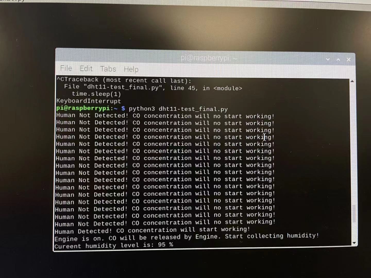
After we connected the photosensitive light sensor and MCP 3008 to the raspberry pi, we found some problems in testing the installation of Adafruit-Blinka. “board” module is not being imported properly, and we updated the pip3 package manager by using “pip3 install –upgrade pip”, then we reinstall the board module and Adafruit-Blinka library to solve this problem.The sample output is showed in Figure 9.
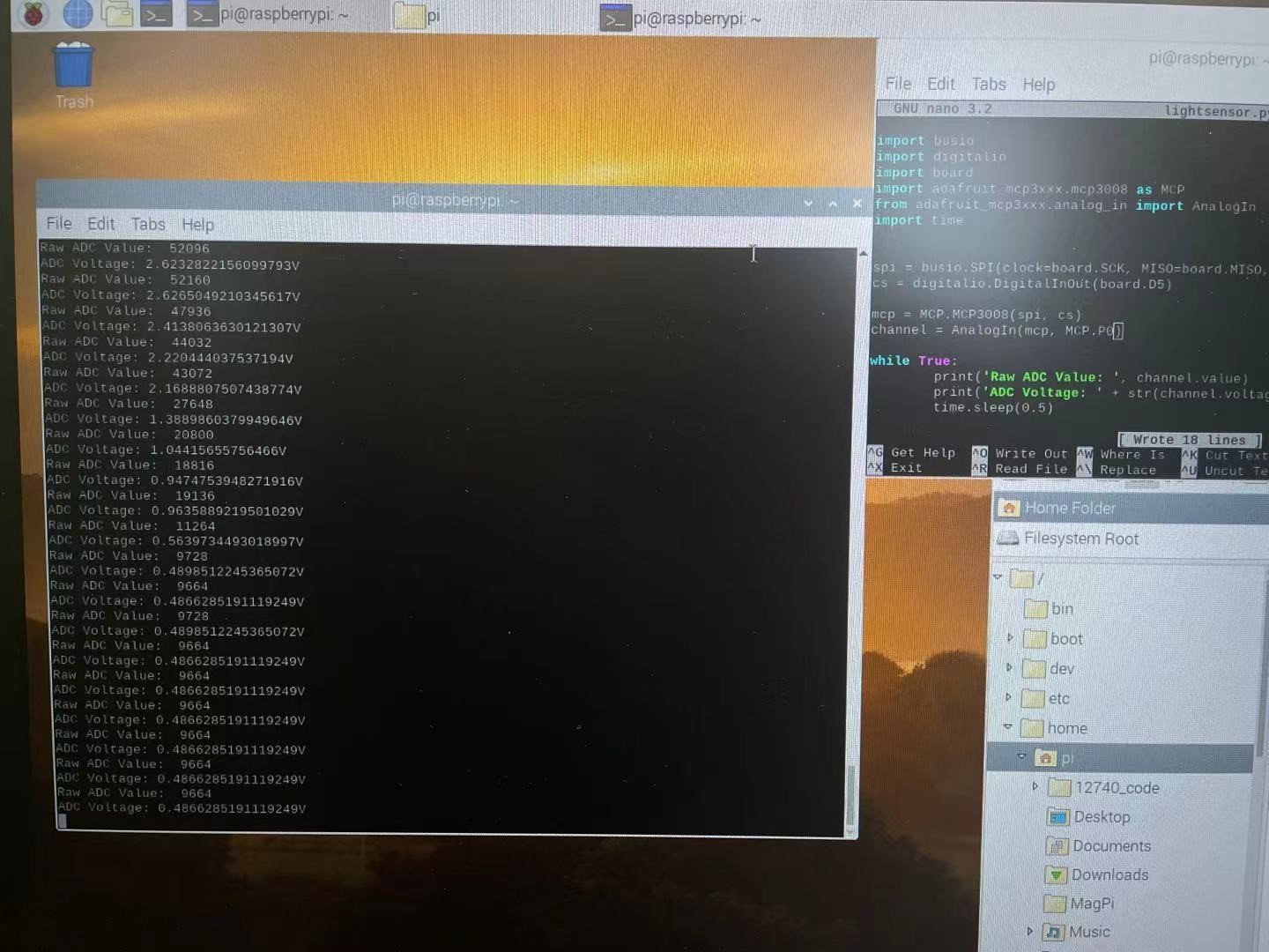
In the output, the ADC voltage will increase as the surrounding light become darker; Decrease as the surrounding light become lighter.
We will use the photosensitive light sensor to detect human occupancy by collecting the data of ADC voltage value. We use a turned-on flashlight point to the sensor so that the value of ADC voltage value will approach 0. When we put the flashlight and sensor inside the vehicle, the ADC voltage will increase when humans are in the vehicle to block the light from a flashlight. So that the system will tell us the human is in the vehicle, and the DHT11 will start collecting the data to test whether the humidity is at the safe level. The red LED will be turned on if the humidity is higher than the safe level.
At this point, our group finished all the circuit setup. And we recorded demo to introduce our project and show how our project actually works.
Methodology
Phenomena of Interest
The CO density (in this case, the humidity), the human occupancy, and the engine status. The gas density can be directly measured. And the engine status can be sensed via either the temperature itself or the temperature of the exhaust. The human occupancy can be determined by whether the light is blocked or not.
In this specific project, the phenomenon itself is not a predominant concern. We are rather more interested in if it exceeds certain threshold. Although we collected the light intensity, the returned value is either “true” or “false”, where “true” stands for human existence. For temperature, if the value is below 25 degree, we can assume the engine is not working. And in the case of CO density (humidity), if it is below 70, we believe the environment is safe.
Sensors Used
In this project, we use light to determine the human occupancy status. A general Photoresistor Sensor works under the following principle. When the photoresistor is blocked by the object, meaning a lower light intensity, the resistance of it is will be extremely high. Otherwise, when the sensor is shined by light, meaning a high light intensity, its resistance will drop down notably [4]. Therefore, we can get the light intensity by measuring the resistance of it at any time.
A temperature sensor is employed to check the engine status. However, considering the range of our sensor which is between 0-50℃, we measure the temperature of the exhaust which is between 30-120℃, instead of directly measuring the engine itself. DHT11 Temperature Sensor has a Negative Temperature coefficient thermistor. When the temperature increases, the resistance of it will decrease. Semiconductor is in the sensor in order to get more accurate changes [5]. So, we can get the temperature of the exhausted gas.
A humidity sensor is utilized to measure the humidity of the ambient humidity. As aforementioned, out of safety concern, we use humidity to substitute the actual CO. Capacity sensor has a moisture holding between two electrodes, and the electrical capacity changes with the atmosphere’s relative humidity [6]. Therefore, we can change the analog signal into digital signal and easily to get the humidity.
Signal Conditioning and Processing
The main decision-making process works as follows:
The photoresistor sensor works to detect the light intensity with the purpose to determine whether there’s a human in the car unless we stop it manually. When the photoresistor sensor detects people, the temperature sensor will work to check the status of the engine. If the temperature of the engine is higher than the threshold, then the humidity sensor will work to detect the humidity (that’s CO density in reality). If the humidity is also higher than the threshold, then an alarming message will show up to suggest people take some measures to make sure of their safety. Here is the flow chart of how the system works.
Experiments and Results
In our project, we will use serval bounded if function to determine whether the assumed closed environment has danger CO concentration level.
The main decision-making process is:
- Use a photosensitive light sensor to determine the human occupancy
- Use DHT11 temperature and humidity sensor to detect the engine working status by measuring the engine temperature
- Use DHT11 temperature and humidity sensor to detect whether the humidity is higher than the threshold value, then conclude the danger level of CO concentration.
Out of safty concern, we measured huumidity instead of CO. That is to say when humidity exceeds certain thershold, the environment will be dangerous to human being.
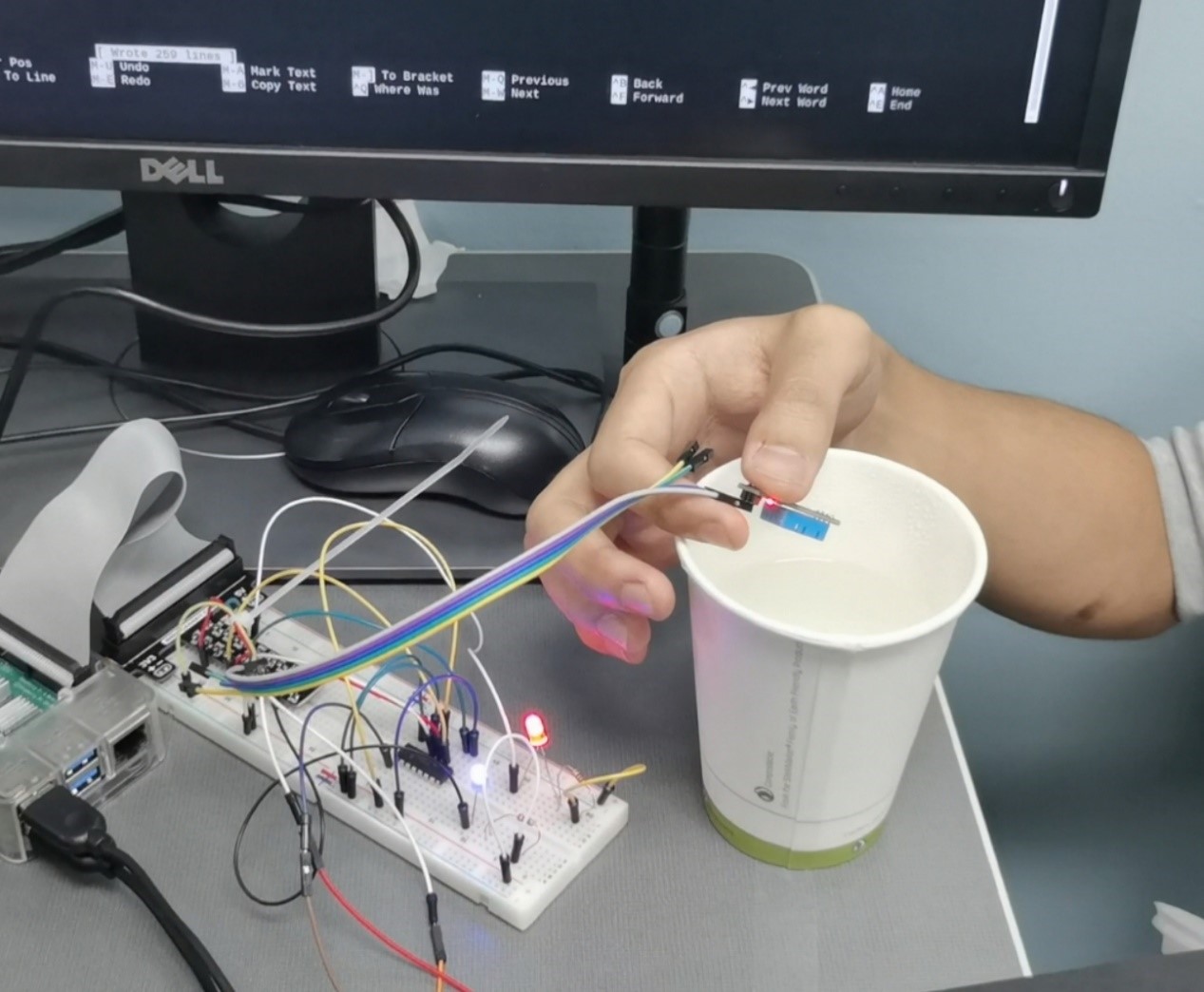
We set up our circuit properly in a closed classroom to meet our project’s closed environment prerequisite condition. Photosensitivity has been fastened on the table; we used a turned-on flashlight to point to the light sensor. The light sensor will receive light to return low ADC values. In this case, we simulate no human in the closed environment if the human body has not blocked the light.
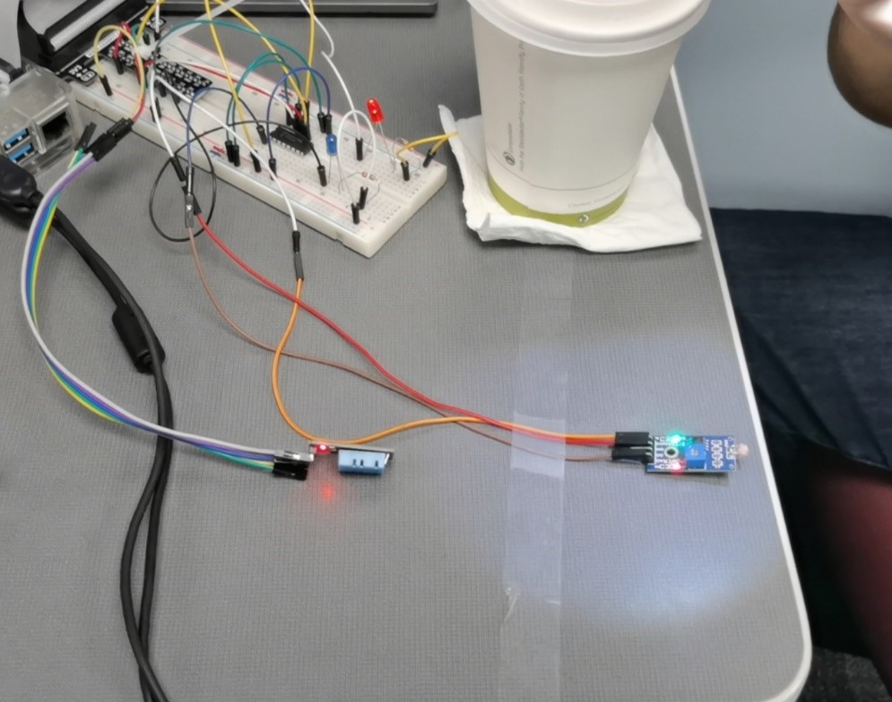
When the human is in this closed environment, the light will be blocked. Then the light sensory will return a high ADC value to prove the human occupancy so that our program will print the human occupancy message and start checking the engine working status by measuring the temperature of the engine. In our experiment, we used a hot water bottle to stimulate the engine to release both heat and CO.
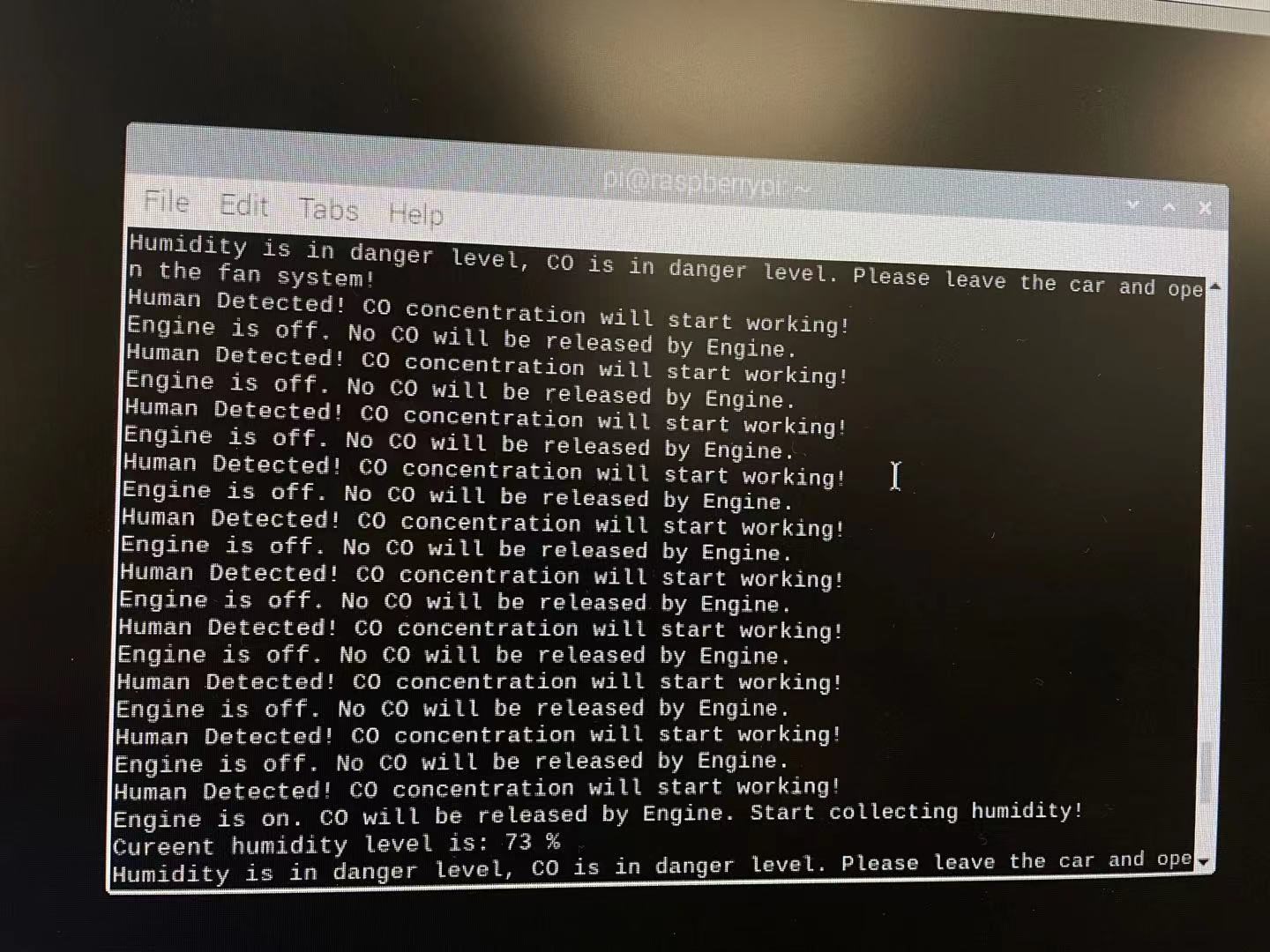
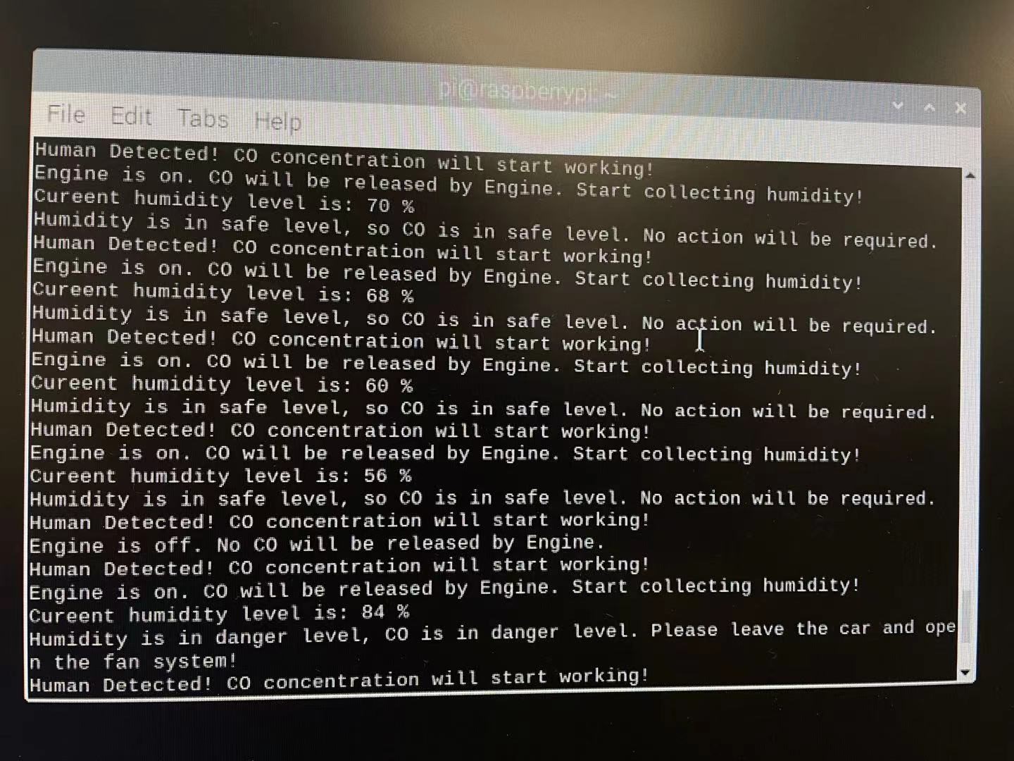
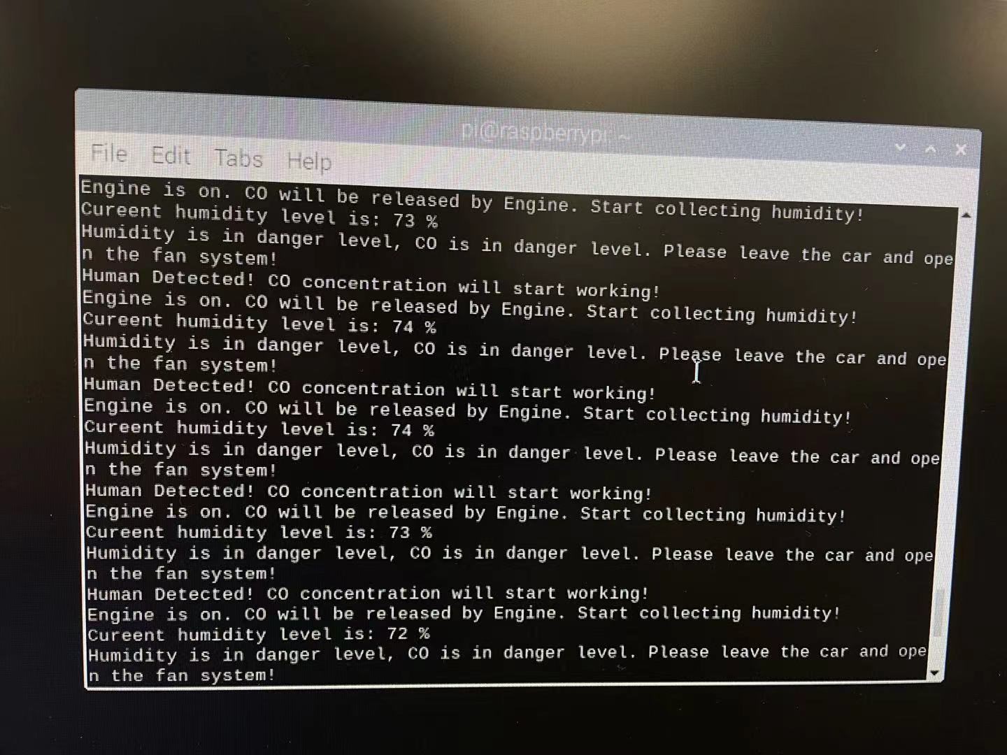
We moved our DHT11 sensor close to the cap for the hot water bottle to receive the heat from the “stimulate engine.” We assume the working temperature of the engine will be 25 degrees Celsius. If the collected temperature data is lower than 25, the program will print the “Engine is off” message to the user, and the humidity will not be collected. When the collected temperature is higher than 25, the blue LED will turn on, and a new message will be sent to say, “Engine is on.” So that the humidity will be collected when the blue LED is on.
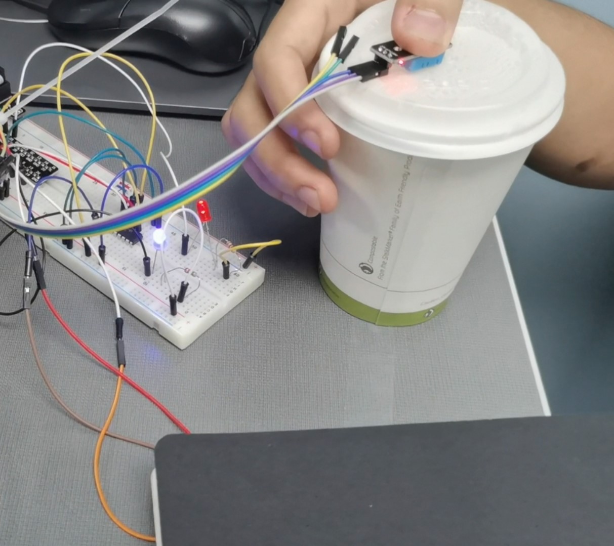
We opened the hot water bottle cap to let the humidity sensor collect the stream of hot water. We used the steam of hot water to represent the CO that is released by the engine, and we assume the danger level of CO concentration will be attained when the humidity is higher than 70%. A danger message will be sent to the user to alarm them the CO centration in the closed environment is at a danger level. The red LED will turn on once the humidity is higher than 70%. Both danger messages and red LED will warn people in this closed environment to leave there to keep them safe.
Discussion
From our project, we found some disadvantages that will cause our photosensitivity sensor to return a wrong value due to the high level of light of the outer environment, for example, the sun light in the daytime without cloud. The light inside the closed environment will be affected by the illumination from outside. The light sensor will still detect human occupancy even though the human has blocked the flashlight since the light inside the closed environment is bright enough to create the wrong message.
So, we think there are two potential ways to improve the precision of human occupancy detection. One is to use an infrared sensor like the motion sensor, which we initially tried to use. This will only detect infrared rays due to the change of human occupancy but not the light in the environment. So, it won’t be affected by the light. The other improvement may be to use a pressure sensor set below the seat of the vehicle. When humans sit down, the pressure sensor will return the real-time weight data of humans, and this will be the other way to prevent the outside environmental factor that will affect the human occupancy detection.
For CO concentration, we don’t have any analysis of the trend of CO concentration increasing or decreasing due to the project’s short time. In real life, the CO concentration usually increases slowly instead of rapidly unless in some specific condition like gas leakage. When the CO increases slowly, humans will not perceive any uncomfortable feeling unless they are inhaled CO for a long time to cause a threat to life. But the CO concentration may also be below the threshold in our project. So, we can add a trend analysis to determine any potential long-term risk. This will prevent humans from the danger that is hard to draw attention to in daily life.
Reference
[1]Centers for Disease Control and Prevention. PICTURE OF AMERICA REPORT. Available from URL:https://www.cdc.gov/pictureofamerica/pdfs/picture_of_america_poisoning.pdf.
[2]MAYO Clinic. (2019, October 16). Carbon monoxide poisoning. Mayo Clinic. Retrieved October 4, 2021, Available from https://www.mayoclinic.org/diseases-conditions/carbon-monoxide/symptoms-causes/syc-20370642.
[3]Iowa State University. (2020). Carbon monoxide poisoning: Vehicles (AEN-208). Department of Agricultural and Biosystems Engineering. Retrieved October 4, 2021, Available from https://www.abe.iastate.edu/extension-and-outreach/carbon-monoxide-poisoning-vehicles-aen-208/.
[4] https://diy.waziup.io/sensors/light/photoresistor.html
[5] https://www.elprocus.com/a-brief-on-dht11-sensor/
[6] https://in.element14.com/sensor-humidity-sensor-technology